Miniature Vacuum Tube Tesla Coil
by Mark S. Rzeszotarski, Ph.D.

Vacuum tube tesla coils operate in a continuous wave mode of operation, continuously providing energy
to the tesla coil secondary. As a result, the output is primarily determined by how much power the
vacuum tube can process.
The spark discharge and operation of these coils is quite different from disruptive coils. If
a D.C. voltage is used to operate the coil, the spark breakout hisses, as opposed to the 60 cycle hum
normally associated with an A.C. operated vacuum tube coil.
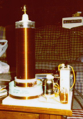
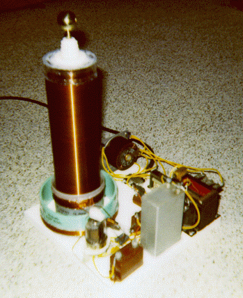
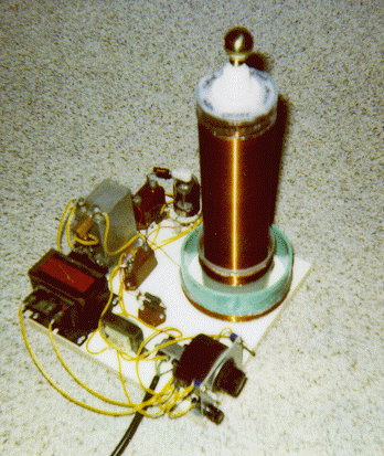
The following text and images describe a small vacuum tube tesla coil which uses a single
6146A or similar beam power vacuum tube. Other television horizontal amplifier tubes can be
readily substituted if desired. The approximate power output is 35 watts, and the unit is capable
of generating a brush discharge of approximately one inch in length. Normally, a small brass knob
is attached to the top of the coil so that spark breakout is inhibited. In this case, considerable R.F.
energy is generated, and luminous tubes (e.g., neon, argon, xenon filled gas tubes) can be readily
ionized and caused to glow while held in the hand several feet away from the coil. This provides
an opportunity for considerable study in a relatively safe operating environment, compared to
most tesla coil systems.
Note that although this coil operates at 620 kilohertz, it is quite capable of causing severe
R.F. burns, and electrocution is also possible due to the high voltages used in its operation. The
information provided here is for educational purposes only. If you are not experienced in the
construction of high voltage apparatus, do not attempt this project! Please also read the
safety FAQ
on tesla coils before you attempt to construct these
devices.
 This tiny vacuum tube oscillator was constructed to evaluate and study
several principles of tesla coil operation.
- The coil is of a slightly different design than the conventional tickler
feedback coil system often published in the literature. In this design, the
grid circuit is the tank circuit, containing the inductor and
capacitor which are tuned to the secondary resonant frequency. Most
published systems use a tuning capacitor in the plate circuit.
- The plate circuit is tightly coupled to the secondary (K=0.22) delivering the energy in the form of short intense R.F. pulses,
operating well into class C with a grid voltage of -68 volts. It is a
D.C. coil, so the pulses occur at a rate of 620,000 times per second.
The plate current averages 100 mA.
- The grid tank circuit is loosely coupled to the secondary (K=0.05) and operates with an
average grid current of 2.5 mA. The grid coil is coupled to the plate coil more tightly
(K=0.14) so that oscillations can be sustained. By using loose coupling in the tank circuit,
frequency stability is less affected when objects are brought near to the coil for experimentation.
- The coil can be operated continuously, since it was designed to be within the maximum limits
for the vacuum tube selected. It was recently powered up for demonstration purposes for
several hours of continuous operation without overheating or malfunction.
- A small coil such as this is advantageous for the study of tesla coil principles, since the output
is on the order of only 12,000-15,000 volts.

- A plastic rod containing a series of 20 or so small NE-2 neon bulbs insulated from each other
can be held next to the coil to demonstrate the voltage rise pattern of the secondary. Since
neons turn on at about 90 volts, the electric field distribution can be studied with this device
near a small coil such as this. The effect is best seen by varying the variac voltage on the high
voltage supply. The voltage distribution follows the properties of a quarter wave helical
resonator, demonstrating a voltage minimum at the base of the secondary coil and a voltage
maximum at the top of the coil. After 15-30 minutes of operation, the temperature of the coil
becomes slightly elevated, and the base is considerably warmer than the top of the coil,
confirming that the current is a maximum at the base and a minimum at the top of the coil.
- Critical components include the grid coil inductance and the grid tank capacitance.
This pair must be tuned to the resonant frequency of the secondary.
- Additional information can be extracted from the
original schematic (42 Kb) or the
cleaner schematic (154 Kb) if desired.
The coil was constructed on a 12" x 12" board using mostly surplus parts.
- Comments, flames and criticisms are welcome via E-mail to
msr7@po.cwru.edu
- Thanks to Chip Atkinson for providing space for the posting of this information.
Copyright © 1997
Mark S. Rzeszotarski, Ph.D.
Cleveland Ohio, U.S.A.
All Rights Reserved.
revised September 3, 1997 by
msr7@po.cwru.edu


 This tiny vacuum tube oscillator was constructed to evaluate and study
several principles of tesla coil operation.
